|
SINGLE LINE SYSTEMS
A
single main line carries lubricant from the pump to the distributors
(Progressive / Injectors), located close to the lubrication points.Grease
in single line systems can be metered through progressive dividers
or injectors or directly to the bearing points through multiline
pumps. Single Line Systems are best suited for small and medium
sized machinery.
Progressive
Type :
 |
The outlets of Progressive Dividers are used as positive metering
devices in single line lubrication systems .The lubricant is forced
into the progressive divider at a single point which is thereafter
progressively distributed among the outlets. The outlets of the
progressive dividers can also be cross-ported in order to feed the
connected bearings at predetermined proportions. The progressive
dividers do not have any "starting" and "stopping " positions. The
piston inside, moves back and forth in series in a continuous cycle,
forcing lubricant successively through the several outlets, as long
as lubricant is supplied at inlet.AFMC manufactures progressive
dividers in two different ranges - 0.2 c.c./outlet and 0.55c.c.
outlet along with pumps and control systems. Progressive systems
can be very conveniently used along with multi line pumps for lubricating
bearings in Bulk Material Handling Equipment, Cement Plant equipment
and also Steel Plant equipment.
Our
Progressive Distributor is a single-line distributor available in
two basic models and rates. IPM and IPL are categorized by their
discharge rates. The Discharge/Outlet of the IPM is 0.55 c.c. and
the IPL is 0.2 c.c. The max. working pressure is 350 bar. The IPL
and IPM models are available with 6,8,10 and 12 outlets. The IPL
- K and IPM - K progressive distributor has got an indicator pin
attached to the end last piston which reciprocates when grease is
discharged from the last outlet and is used for monitoring purposes
with the help of a limit/proximity switch.
| ^TOP |
| <PRODUCTS
INDEX |
|
A
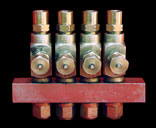
main-line carries lubricant from the pump to the distributors
(Injectors) situated close to the lubrication points. Each
point has its own metering element. The lubrication cycle
consists of a compression stroke and after the metering elements
have discharged, a relief stroke.Injector type Systems are
best suited for small & medium sized machinery.
AFMC manufactures a wide range of injectors with discharge
rates from .05 to 1.3 c.c./stroke along with pumps & control
systems.
| S.No. |
Model
No. |
Max.Discharge/cycle |
Working |
Pressure |
Max
Venting Pr. |
| |
|
|
Max |
Min |
|
| 1. |
SL
- 32 |
0.13
c.c. |
250
bar |
85
bar |
15
bar |
| 2. |
SL
- 33 |
0.05
c.c. |
250
bar |
85
bar |
15
bar |
| 3. |
SL
43L |
0.13
c.c. |
200
bar |
45
bar |
85
bar |
| 4. |
SL
- 1 |
0.13
1.3 c.c. |
246
bar |
130
bar |
|
|
| |
| ^TOP |
|
| <PRODUCTS
INDEX |
Multi Line Pumps :
 |
The Multi-line pump can accommodate up to 30
pumping units. The delivery pump comprises of the following major
components: pump housing, pump elements, internal and external drive
and reservoir. The vertical pump is driven by an external drive via
a worm gear. An eccentrically arranged pressure ring rotates with
this pump shaft engaging the pumping elements. The eccentricity of
this pressure ring causes each supply piston to perform one constant
pressure and suction stroke per pump shaft rotation. The discharge
per outlet per hour can be varied between 6 c.c.- 210 c.c. and 12
c.c.- 420 c.c. by changing the gear ratio in the Gear Box and Pump.The
multi-line pump is available in 10,15, 20 and 30 outlet models with
two types of drive motor positioning. In type GM the motor is vertically
flange mounted and type G the motor is horizontally flange mounted
The maximum working pressure of the pump is 350 Bar and there is a
reservoir capacity option of 15 Ltrs. and 10 Ltrs & 30 ltrs.A
Gear Ratio to Discharge chart is given below:
| HOURLY
DISCHARGE RATES: |
|
GEAR
RATIO
|
M
series
|
M-
F Series
|
| Gear
Box |
Pump
|
Discharge/Outlet/
Hour (c.c.) (Adjustable) |
Discharge/Outlet/
Hour (c.c.) (Adjustable) |
| 44:1
|
44:1
|
6
|
12
|
| 10:1
|
44:1
|
28
|
56
|
| 6:1
|
44:1
|
48
|
96
|
| 3:1
|
44:1
|
96
|
192
|
| 10:1
|
10:1
|
126
|
252
|
| 6:1
|
10:1
|
210
|
420
|
|
Multi
Line Pump Models
|
S.No.
|
Model
No.
|
No.
Of Outlets
|
Max.Discharge/Outlet/Stroke
|
|
1.
|
M-10
|
10
|
0.15
c.c.
|
|
2.
|
M-10
F
|
10
|
0.3
c.c.
|
|
3.
|
M-15
|
15
|
0.15
c.c.
|
|
4.
|
M-15
F
|
15
|
0.3
c.c.
|
|
5.
|
M-20
|
20
|
0.15
c.c.
|
|
6.
|
M-20
F
|
20
|
0.3
c.c.
|
|
7.
|
M-30
|
30
|
0.15
c.c.
|
|
8.
|
M-30
F
|
30
|
0.3
c.c.
|
|
^TOP
|